A tolerance of ±0.005 mm looks unambiguous on a drawing, yet its manufacturing meaning changes with the feature being measured. A bore diameter, the position of that bore relative to a datum, and the profile of a curved surface are different inspection problems.
Even a sophisticated machine cannot compensate for unclear references or a dimension that cannot be verified consistently. Engineers assessing 5 axis CNC machining services therefore need to examine how the part is located, cut, and measured, rather than treating a supplier’s smallest advertised number as a universal specification.
What Does the Drawing Actually Control?
Dimensional tolerance defines the permitted variation of a size; geometric tolerance governs matters such as location, orientation, and form. A hole may have an acceptable diameter but still fail assembly because its axis is misplaced. Similarly, a surface profile requirement must refer to an appropriate datum system if inspection results are to mean the same thing at both facilities.
Not every surface warrants the same limit. Sealing faces, locating bores, and mating features often justify tighter control than nonfunctional exterior contours. Distinguishing critical from general dimensions reduces ambiguity during quoting and prevents the inspection plan from concentrating on details that do not govern fit. The drawing should also specify whether a finish or subsequent treatment affects the final acceptance condition.
How Do Rotary Axes Change the Tolerance Stack?
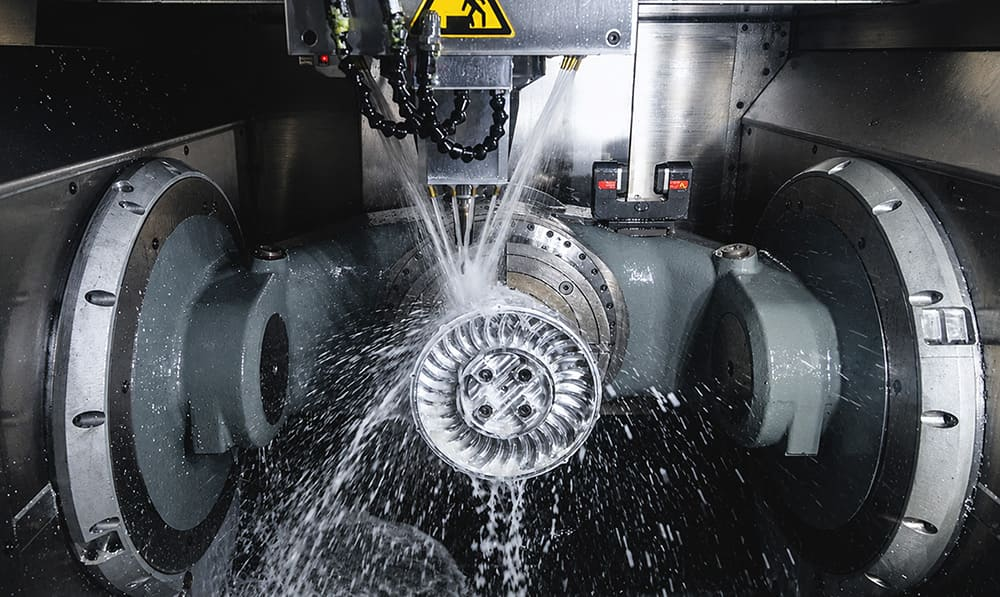
A five-axis machine moves along X, Y, and Z while using two rotary axes to orient the workpiece or tool. Compound angles and features on several faces may then be reached without repeatedly removing and repositioning the part. Fewer setups can reduce the number of opportunities for location error, especially when features must maintain a common datum relationship.
That advantage has limits. Rotary-axis calibration, fixture rigidity, tool length, collision clearance, and cutter deflection still influence results. The workholding scheme should preserve accessible reference surfaces throughout the cutting sequence.
For components with curved walls or intersecting holes, 5 axis CNC machining services are most useful when the chosen machine motion supports the actual tolerance relationships, not merely because the geometry appears complicated.
Why Do Material and Geometry Change the Result?
A thin aluminum wall can move under cutting force or spring back after a clamping load is released. Titanium and nickel alloys present different heat and tool-wear challenges, while engineering plastics may respond strongly to temperature and fixturing pressure.
Tool engagement and part stiffness must therefore be considered together with the nominal tolerance callout. A tightly toleranced part may also need time to reach a stable shop temperature before final measurement. Otherwise, differences between cutting conditions and inspection conditions can obscure whether the feature actually meets the specified limit.
Small internal corners, deep cavities, long-reach cutters, and interrupted surfaces complicate the cut further. A feature that is readily accessible with a short, rigid tool may require a different machining strategy when surrounded by tall walls. Process planning should identify which limits are realistic in the as-machined condition and which require a distinct finishing or inspection operation.
What Inspection Evidence Can Support a Tight Claim?
Capability figures are meaningful only when matched to a specific characteristic and measurement method. Hanstar Technologies quotes ±0.005 mm as a standard tolerance for its five-axis service, with capability down to ±0.002 mm on selected critical features under suitable conditions. Neither figure should be interpreted as the achievable limit for every material, size, and surface on a drawing.
Its equipment includes Hermle C22U, C42U, C42UMT, C52UMT, and C62UMT machining centers, as well as a Mikron MILL E 500U. For verification, the inspection team uses Zeiss CONTURA coordinate-measuring equipment, a Hexagon Absolute Arm, vision systems, and precision gauges. Measurement reports, first-article records, and conformity documentation can be requested according to the project.
Inspection should be planned around the datum scheme and the actual feature, with measurement uncertainty considered before judging borderline results. The chosen instrument must have sufficient resolution and a documented measurement method for the acceptance limit.
What Belongs in a Feasibility Review?
A complete submission includes the 3D model, a dimensioned drawing, material grade, required finish, and an explicit list of critical features. STEP, IGES, Parasolid, or native CAD formats can convey geometry, but the drawing still needs to define acceptance criteria.
The engineer reviewing 5 axis CNC machining services can then assess tool access, datum continuity, proposed setups, and whether any dimension requires special inspection. Hanstar Technologies also considers wall stability and finishing needs when examining such inquiries; a tolerance taken before anodizing or coating may not describe the dimension expected at final acceptance.
Prototype quantities can be useful for verifying an ambitious tolerance scheme before repeating the process. An inspection result that challenges the drawing may reveal a datum problem or measurement mismatch rather than a machining failure. The practical goal is agreement on which characteristics matter, how they will be produced, and what evidence will demonstrate conformity.
For complex components, a defensible tolerance plan joins design intent with realistic cutting conditions and measurable acceptance limits. Engineering teams can request a targeted five-axis feasibility review from Hanstar Technologies for the datum or profile callout that will govern final inspection.
