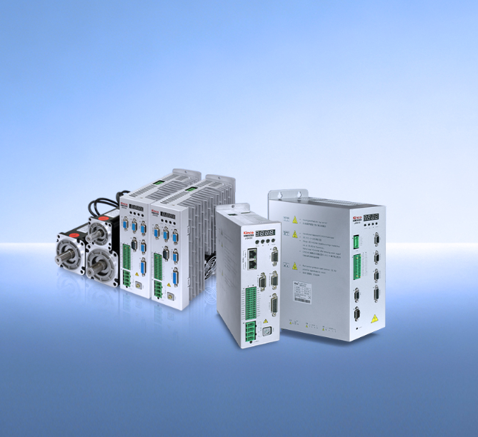
A servo motor driver does not simply turn the motor on and off. It reads position feedback, calculates error, adjusts current, and repeats this cycle thousands of times per second — all to keep the motor within the required positioning tolerance.

The Control Loops That Make Precision Possible
The question is not whether a servo system is accurate, but how the AC servo drive itself makes that accuracy possible. Understanding the internal mechanisms reveals why some drives deliver tighter positioning than others, and what specifications actually matter when motion precision is on the line.
The current loop is the innermost and fastest loop. It controls the current delivered to the motor windings, which directly determines torque. This loop operates at the highest frequency — typically tens of kilohertz — because torque must respond almost instantly to changes in load or command. A well-tuned current loop helps reduce torque fluctuations that can contribute to low-speed vibration and audible noise.
The speed loop sits one level above. It compares the actual motor velocity against the commanded speed and adjusts the current loop’s torque reference accordingly. The speed loop’s response frequency determines how quickly the motor can recover from speed deviations caused by load changes or friction.
For the Kinco JD series, the speed loop response frequency reaches 660 Hz — a specification that directly indicates how fast the drive can react to disturbances and restore the commanded velocity.
The position loop is the outermost loop and the one most directly responsible for final positioning accuracy. It compares the actual rotor position — read from the encoder — against the target position and generates a speed command for the speed loop.
The position loop’s gain settings determine how aggressively the drive corrects positional errors. Too low, and the system lags; too high, and it oscillates. The driver’s ability to tune these three loops independently — and to do so digitally rather than with fixed analog components — is what separates modern servo drives from earlier generations.
How Faster Response Translates to Tighter Accuracy
Response frequency is not an abstract number. It defines how quickly the driver can detect an error and act on it. The significance of a 660 Hz speed loop is its ability to respond quickly to disturbances such as load changes, friction variations, and material tension.
This responsiveness matters because motion errors do not announce themselves in advance. A load change on a conveyor, a friction spike in a linear guide, or a variation in material tension all introduce disturbances that push the motor off its intended trajectory. The driver’s job is to catch those deviations and cancel them before they accumulate into measurable positioning errors.
The practical implication is visible in applications like CNC machining or laser cutting, where path accuracy determines finished part quality. A driver with a 660 Hz speed loop can maintain tighter velocity regulation during contouring moves, reducing the scalloping effect that occurs when the tool path deviates from the programmed trajectory. This is not about peak torque or maximum speed — it is about how well the driver holds the commanded motion profile under real operating conditions.
Higher loop bandwidth can shorten the time between disturbance detection and correction, helping the system maintain tighter motion control when the mechanical system and tuning can support it. The final positioning accuracy depends on mechanical stiffness, encoder resolution, load inertia, and controller tuning working together with the drive’s capabilities.
The Feedback Chain: From Encoder to Correction
Accuracy ultimately depends on knowing where the motor actually is. The driver reads position from an encoder mounted on the motor shaft — or in some cases, directly on the load — and uses that feedback as the basis for all three control loops. The encoder’s resolution sets a fundamental limit on how finely the driver can resolve position.
Higher resolution means smaller position increments per encoder pulse, which allows the driver to detect and correct smaller errors. The Kinco JD series supports communication-type high-resolution encoders, including incremental and absolute encoders with SSI, BiSS, and ENDAT protocols.
The driver’s internal processing determines how effectively feedback is used. The JD series employs optimal PID algorithms to complete current loop, speed loop, and position loop regulation. Digital implementation allows parameters to be adjusted precisely for each application — a flexibility that analog servo systems cannot provide.
Beyond the motor-mounted encoder, some architectures incorporate a second feedback device directly on the load. This creates a full-closed-loop system that compensates for mechanical transmission errors such as ball screw backlash or belt stretch.
The JD series supports full closed-loop control, allowing the driver to correct errors that occur after the motor shaft — a capability that is essential for applications where the load and the motor are not rigidly coupled.
Beyond the Single Axis: Synchronization and System-Level Accuracy
Motion accuracy in multi-axis systems depends on more than each driver’s individual performance. Axes must move in coordinated patterns — circular interpolation in CNC, synchronized rollers in printing presses, coordinated joints in robotics — and any timing mismatch between axes produces path errors that no single-axis tuning can fix.
The driver’s communication interface determines how well axes stay synchronized. The JD series supports CANopen and MODBUS protocols, with independent master-slave following hardware interfaces that ensure high-precision, high-speed following performance. This hardware-level synchronization reduces the communication jitter that would otherwise introduce timing variations between axes.
The cumulative effect of these capabilities — high loop frequencies, high-resolution encoder support, full closed-loop control, and deterministic communication — is a system where each axis responds predictably and in sync with the others. That predictability is what enables the path accuracy required in precision manufacturing and the smooth coordinated motion demanded by robotic systems.
Precision as a System Property
In practice, the driver’s value is determined by how effectively its control loops, feedback system, and communication architecture work together under the actual load. Specifications such as 660 Hz speed-loop response or encoder compatibility matter only when they translate into lower tracking error, faster settling, and more stable multi-axis motion.
The servo motor driver does not guarantee accuracy on its own — but without the right driver capabilities, even the best motor and mechanical design will fall short of its precision potential.
